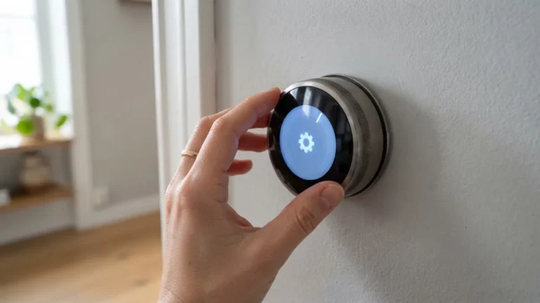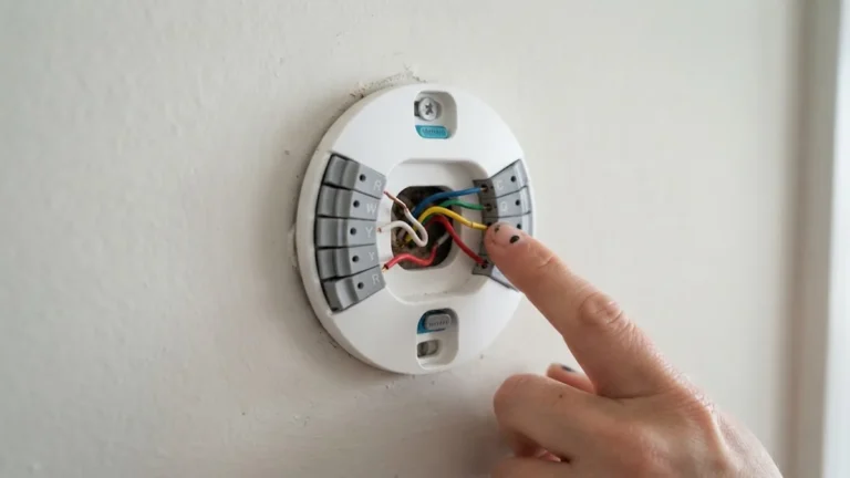

A thermostat wiring diagram looks confusing at first glance: a handful of colored wires, a row of letters like R, C, W, Y and G, and a warning not to mix anything up. Once you know what each letter does, though, almost every home heating and cooling system follows the same simple logic.
This guide explains every common thermostat terminal, shows typical wiring diagrams for a furnace with central air and for a heat pump, and covers thermostat wire types, the C wire, and how to swap thermostats without guessing. It is written for homeowners replacing an old thermostat or installing a smart one, and it points out clearly where a professional should take over.
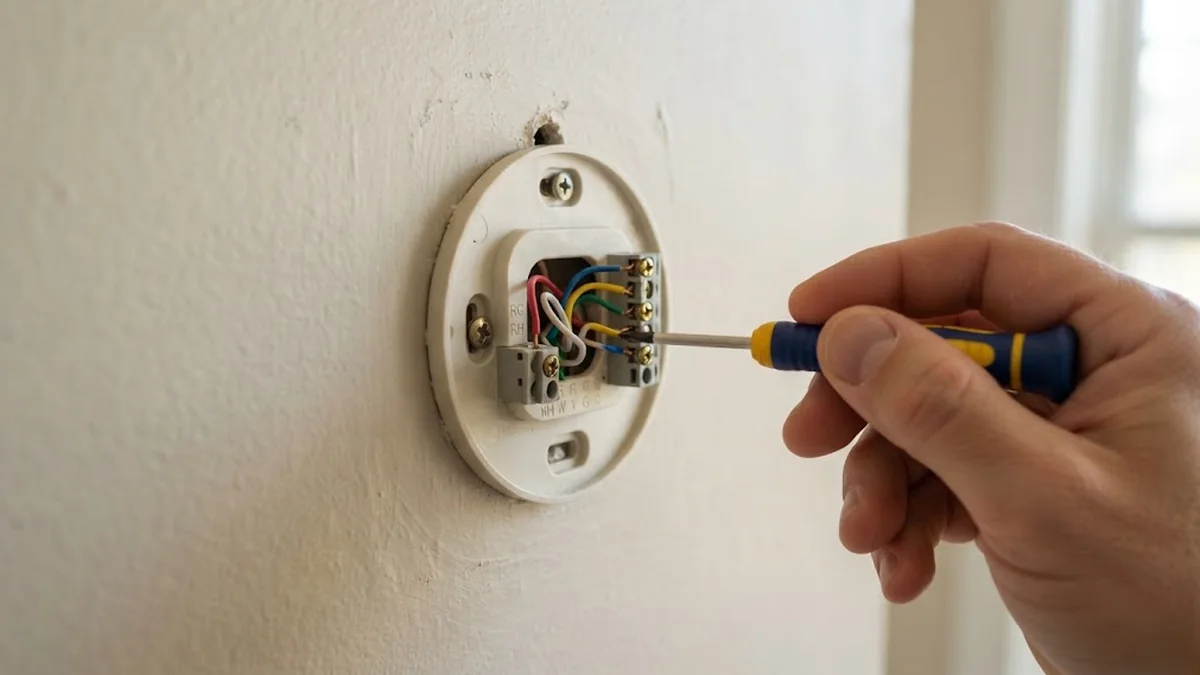
Table of Contents
- Safety First: Before You Touch Any Wires
- Thermostat Wire Color Code and Terminal Letters
- Thermostat Wiring Diagram: Gas Furnace With Central Air
- Thermostat Wiring Diagram: Heat Pump
- Other Common Setups
- Thermostat Wire Types and Gauge
- The C Wire: Why Smart Thermostats Need It
- How to Replace a Thermostat Using Your Wiring Diagram
- Troubleshooting Wiring Problems
- Low-Voltage vs Line-Voltage Thermostats
- Tools You Need for Thermostat Wiring
- How to Label and Photograph Your Wires
- Frequently Asked Questions
- Final Thoughts
Safety First: Before You Touch Any Wires
Most home thermostats run on low voltage, about 24 volts AC, supplied by a small transformer in your furnace or air handler. That is far safer than household wiring, but it can still damage equipment if a wire touches the wrong terminal. Honeywell Home’s thermostat wiring guide recommends a few basics:
Installing a Google Nest? Follow our step-by-step Nest thermostat wiring guide.
- Turn off power to the HVAC system at the breaker or the service switch near the furnace.
- Confirm it is off. Change the set point on the old thermostat and make sure nothing starts within five minutes.
- Photograph the existing wiring with the terminal letters visible before you disconnect anything.
- Label each wire by its terminal, not by its color. A small piece of tape and a pen are all you need.
- Check for line voltage. Thick black or red wires connected with wire nuts usually mean a 120V or 240V line voltage thermostat, common with baseboard heaters. Low voltage thermostats cannot be used on these systems.
If you have a dual fuel system (a heat pump plus a gas or oil furnace), a boiler with special controls, or you simply are not sure what you have, call an HVAC technician.
Thermostat Wire Color Code and Terminal Letters
Here is the most important rule in this whole guide: there is no official color standard for thermostat wires. Installers usually follow common habits, but older homes and DIY repairs often break them. Always go by the letter of the terminal the wire is connected to.
With that in mind, here are the usual pairings:
| Terminal | Typical wire color | What it does |
|---|---|---|
| R | Red | 24V power from the transformer |
| Rh / Rc | Red | Separate power for heating (Rh) and cooling (Rc) in two transformer systems |
| C | Blue or black | Common wire that completes the 24V circuit; powers smart thermostats |
| W / W1 | White | First stage heat |
| W2 / AUX | Brown, white or other | Second stage or auxiliary heat |
| Y / Y1 | Yellow | First stage cooling (compressor) |
| Y2 | Light blue or other | Second stage cooling |
| G | Green | Indoor blower fan |
| O/B | Orange (O) or dark blue (B) | Heat pump reversing valve |
| E | Varies | Emergency heat on heat pumps |
The heating and cooling services company Aire Serv makes the same point in its wire color guide: colors vary, and a wire’s color may not match the terminal it lands on if someone swapped or spliced wires in the past.
R, Rh and Rc explained
Most systems have one transformer, so you will see a single R wire or a small jumper linking Rh and Rc. Some older homes with separate heating and cooling equipment have two transformers. In that case you will find two red wires, one on Rh and one on Rc, and the jumper must be removed. If your new thermostat has only one R terminal and you have two R wires, check its manual before going further.
Thermostat Wiring Diagram: Gas Furnace With Central Air
This is the most common setup in North American homes. A typical five wire system connects like this:

- R (red) to R: power
- C (blue) to C: common, needed by most smart thermostats
- W (white) to W: calls for heat from the furnace
- Y (yellow) to Y: calls for cooling from the outdoor AC unit
- G (green) to G: runs the indoor fan
If you only have four wires (R, W, Y and G) there is no C wire. Many smart thermostats need one; see the C wire section below.
Thermostat Wiring Diagram: Heat Pump
A heat pump uses the same outdoor unit to heat and cool, so wiring looks a little different. Instead of W calling for heat, the thermostat uses Y for the compressor in both modes and the O/B wire to switch the reversing valve.

- R to R and C to C, as before
- Y (yellow) to Y: compressor for heating and cooling
- G (green) to G: fan
- O/B (orange) to O/B: reversing valve
- W2 or AUX (often white or brown) to AUX or W2: backup electric or gas heat
Most brands energize the reversing valve in cooling mode (O), while some, including older Rheem and Ruud systems, energize it in heating mode (B). Your new thermostat will ask during setup; if heating and cooling seem reversed after installation, this setting is usually the fix. Our roundup of the best smart thermostats notes which models handle heat pumps and multi stage systems well.
Other Common Setups
Heat only (furnace or boiler)
Two wires are typical: R and W. Some boilers use a two wire circuit with no C wire at all. Smart thermostats on these systems often need an adapter or a model with a battery or power stealing design.
Two stage heating or cooling
Two stage systems add W2 for a second heating stage and Y2 for a second cooling stage. Connect each wire to the matching terminal, and enable two stage operation in the thermostat’s setup menu.
Systems with a humidifier or ventilator
Some thermostats have an accessory terminal (often labeled U or ACC) for a humidifier, dehumidifier or ventilator. Check both the thermostat and the accessory manual before connecting it.

Thermostat Wire Types and Gauge
When you open the wall plate you will usually see a single cable with several thin, solid copper conductors inside. Honeywell Home notes that most homes use 18 gauge solid core thermostat wire, typically with about five conductors, although anything from two to ten is possible.
If you are running new thermostat wire, a few tips help:
- Buy 18 gauge (18/5, 18/7 or 18/8). The second number is the conductor count. Extra conductors cost little and make future upgrades easy.
- Use solid copper, not stranded. Solid wire seats firmly in thermostat terminals.
- Pick CL2 or CL3 rated cable for in-wall runs, as required by most building codes.
- Leave spare conductors coiled and labeled at both ends. A spare is the easiest way to add a C wire later.
The C Wire: Why Smart Thermostats Need It
Older thermostats run on batteries or tiny amounts of power from the heating circuit. Smart thermostats with Wi-Fi and touchscreens need steady power, which the C (common) wire provides.
If you do not have a C wire, you have four main options:
- Use a spare conductor in the existing cable, connected to C at both the thermostat and the furnace board.
- Install a C wire adapter (sometimes called a power extender kit), which many thermostat brands include in the box.
- Run a new cable with more conductors.
- Choose a thermostat designed to work without a C wire.
If you want energy savings to justify the upgrade, look for an ENERGY STAR certified smart thermostat; these are certified using real field data. Our full guide to smart thermostats with no C wire compares these options in detail.
How to Replace a Thermostat Using Your Wiring Diagram
- Turn off power and confirm the system will not start.
- Remove the old thermostat face and photograph the wiring.
- Label each wire with its terminal letter.
- Unscrew the terminals and remove the old wall plate. Wrap the cable around a pencil so it cannot fall into the wall.
- Mount the new wall plate, using a level.
- Connect each labeled wire to the matching terminal on the new thermostat.
- Attach the thermostat and restore power.
- Run the setup wizard, confirming your system type (conventional or heat pump) and stages.
- Test heat, cool and fan one at a time.
Before buying, use the brand’s online compatibility checker, such as Google Nest’s compatibility tool, to make sure your wiring works with the model you want. For a complete walk through with photos, see our smart thermostat installation guide.
Troubleshooting Wiring Problems
- Nothing turns on: Check the breaker, the furnace door safety switch and the R wire. A blown low voltage fuse on the control board is also common after wiring mistakes.
- Fan runs all the time: The G wire may be on the wrong terminal, or the fan setting is on rather than auto.
- Heat pump blows cold in heat mode: The O/B setting is reversed in the thermostat menu.
- Thermostat screen goes blank: No C wire, or a loose C connection.
- AC does not start: Check the Y wire at both ends and wait five minutes for compressor protection.
If you see a burned smell, a melted wire or a fuse that keeps blowing, stop and call a technician.
Low-Voltage vs Line-Voltage Thermostats
Every diagram in this guide is for low-voltage (24V) thermostats, the type used with most furnaces, central air systems, heat pumps and boilers. These have thin, colour-coded wires bundled in one cable.
Line-voltage thermostats are different. They control electric baseboard heaters, fan heaters and some radiant floors directly at 120V or 240V. You can usually spot one because it has two or four thick wires, often black and red or black and white, joined with wire nuts rather than small screw terminals.
- Never connect a standard 24V smart thermostat to line-voltage wires. It will be destroyed and can be a fire and shock risk.
- Use a thermostat made for line voltage. Brands such as Mysa make smart thermostats designed for electric baseboard heating.
- Turn the power off at the breaker, not just at the thermostat, and check with a non-contact voltage tester before you touch anything.
If you aren’t sure which type you have, take a photo of the wires and the old thermostat’s label, and check the label for a voltage rating before buying a replacement.
Tools You Need for Thermostat Wiring
Most low-voltage thermostat swaps need only a few basic tools:
- A small flat-head and Phillips screwdriver
- A non-contact voltage tester
- Wire labels or masking tape and a pen
- Wire strippers, for trimming damaged wire ends
- A drill and wall anchors, if the new base plate uses different holes
- Your phone, to photograph the old wiring before you disconnect anything
Many smart thermostats include wire labels in the box. Use them, even if you think you’ll remember, and keep the photo of the old wiring until the new thermostat has run through a full heating and cooling cycle. A single swapped wire is the most common reason a new thermostat won’t heat or cool.
How to Label and Photograph Your Wires
Good notes turn a confusing job into a simple one. Before disconnecting anything:
- Take a clear photo of the thermostat wiring with the cover off, so every letter and wire colour is visible.
- Write down which colour goes to which letter, for example “Red to R, White to W, Yellow to Y, Green to G, Blue to C”.
- Note any jumper wire between R and Rc or Rh. You may need to reproduce it on the new thermostat.
- Label each wire by the terminal letter, not the colour. Installers don’t always follow the colour code.
- If there’s an unused wire tucked into the wall, note that too. It might become your C wire later.
For a full walkthrough of a smart thermostat swap, see our smart thermostat installation guide.
Frequently Asked Questions
What color wire goes to R on a thermostat?
Usually red. If you have two red wires, one may go to Rh (heating) and one to Rc (cooling). Always check which terminal each wire was on before disconnecting.
Can I use a thermostat without a C wire?
Many basic and some smart thermostats work without one, but a C wire gives the most reliable power. Adapters and spare conductors are the usual fixes.
What if my wire colors do not match the diagram?
Ignore the colors and go by the terminal letters on your old thermostat and your furnace control board. Colors are not standardized.
What does the O/B wire do?
It controls the reversing valve on a heat pump, which switches the system between heating and cooling. It is not used on a conventional furnace and AC system.
How many wires does a thermostat need?
It depends on the system. A heat only boiler may need two, a typical furnace and AC system uses four or five, and a multi stage heat pump can use eight or more.
Can I mix up the Y and G wires?
Swapping them can make the fan and compressor behave strangely, and in some cases run the compressor without airflow. Double check both before restoring power.
How do I know if my thermostat is line voltage?
Line-voltage thermostats usually control electric baseboard heaters and have thick wires joined with wire nuts. Low-voltage thermostats have thin colour-coded wires on small screw terminals. Check the old thermostat’s label for 120V or 240V before replacing it.
Should I hire an electrician for thermostat wiring?
A like-for-like swap of a 24V thermostat is a common DIY job. Call a professional for line-voltage systems, new wire runs, adding a C wire at the furnace board, or if wires look burned or damaged.
What gauge is thermostat wire?
Most residential thermostat cable is 18-gauge (18 AWG) solid copper, labelled by the number of conductors, such as 18/5 for five wires. When running a new cable, choose one with at least one or two more wires than you need now, so you have a spare for a C wire or future upgrades.
Final Thoughts
A thermostat wiring diagram becomes simple once you remember three rules: turn off the power, label every wire by its terminal letter, and ignore the colors if they do not match the usual pattern. With that in hand, swapping a thermostat is a manageable weekend job. If you are choosing a new model, our comparison of Nest vs Ecobee and our list of budget smart thermostats will help you pick one that suits your wiring, and our guide to smart thermostat energy savings shows what you can expect to save.